Points de contrôle
Enable required APIs
/ 25
Prepare your environment
/ 25
Install GKE Service Mesh
/ 25
Deploy the Cymbal Bank application
/ 25
Manage and Secure Distributed Services with GKE Managed Service Mesh
GSP1242

Overview
GKE Service Mesh is based on the open source Istio technology. A distributed service is a Kubernetes Service that acts as a single logical service. These services are more resilient than Kubernetes services because they operate on multiple Kubernetes clusters in the same namespace. A distributed service remains operational even if one or more GKE clusters are down, as long as the healthy clusters serve the expected load.
GKE private clusters allow you to configure the nodes and API server as private resources available only on the Virtual Private Cloud (VPC) network. Running distributed services in GKE private clusters gives enterprises secure and reliable services.
This lab teaches you how to run distributed services on multiple Google Kubernetes Engine (GKE) clusters in Google Cloud. You will learn how to expose a distributed service using Multi Cluster Ingress and GKE Service Mesh.
Objectives
In this lab, you learn how to perform the following tasks:
- Create three GKE clusters.
- Configure two of the GKE clusters as private clusters.
- Configure one GKE cluster (gke-ingress) as the central configuration cluster.
- Configure networking (NAT Gateways, Cloud Router, and firewall rules) to allow inter-cluster and egress traffic from the two private GKE clusters.
- Configure authorized networks to allow API service access from Cloud Shell to the two private GKE clusters.
- Deploy and configure multi-cluster GKE Service Mesh to the two private clusters in multi-primary mode.
- Deploy the Cymbal Bank application on the two private clusters.
Scenario
In this lab you will deploy the Cymbal Bank sample application on two GKE private clusters. Cymbal Bank is a sample microservices application that consists of multiple microservices and SQL databases that simulate an online banking app. The application consists of a web frontend that clients can access, and several backend services such as balance, ledger, and account services that simulate a bank.
The application includes two PostgreSQL databases that are installed in Kubernetes as StatefulSets. One database is used for transactions, while the other database is used for user accounts. All services except the two databases run as distributed services. This means that Pods for all services run in both application clusters (in the same namespace), and GKE Service Mesh is configured so that each service appears as a single logical service.
Setup and requirements
Before you click the Start Lab button
Read these instructions. Labs are timed and you cannot pause them. The timer, which starts when you click Start Lab, shows how long Google Cloud resources will be made available to you.
This Qwiklabs hands-on lab lets you do the lab activities yourself in a real cloud environment, not in a simulation or demo environment. It does so by giving you new, temporary credentials that you use to sign in and access Google Cloud for the duration of the lab.
What you need
To complete this lab, you need:
- Access to a standard internet browser (Chrome browser recommended).
- Time to complete the lab.
Note: If you already have your own personal Google Cloud account or project, do not use it for this lab.
Note: If you are using a Pixelbook, open an Incognito window to run this lab.
How to start your lab and sign in to the Google Cloud Console
-
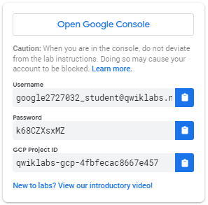
Click the Start Lab button. If you need to pay for the lab, a pop-up opens for you to select your payment method. On the left is a panel populated with the temporary credentials that you must use for this lab.
-
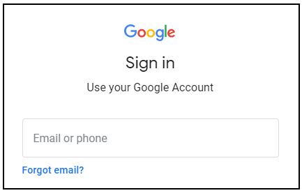
Copy the username, and then click Open Google Console. The lab spins up resources, and then opens another tab that shows the Sign in page.
Tip: Open the tabs in separate windows, side-by-side.
-
In the Sign in page, paste the username that you copied from the Connection Details panel. Then copy and paste the password.
Important: You must use the credentials from the Connection Details panel. Do not use your Qwiklabs credentials. If you have your own Google Cloud account, do not use it for this lab (avoids incurring charges).
-
Click through the subsequent pages:
- Accept the terms and conditions.
- Do not add recovery options or two-factor authentication (because this is a temporary account).
- Do not sign up for free trials.
After a few moments, the Cloud Console opens in this tab.
Activate Cloud Shell
Cloud Shell is a virtual machine that is loaded with development tools. It offers a persistent 5GB home directory and runs on the Google Cloud. Cloud Shell provides command-line access to your Google Cloud resources.
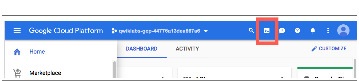
In the Cloud Console, in the top right toolbar, click the Activate Cloud Shell button.
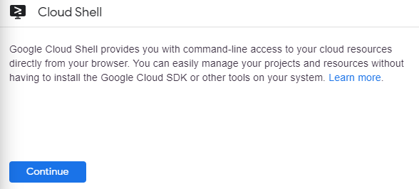
Click Continue.
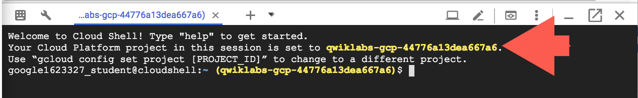
It takes a few moments to provision and connect to the environment. When you are connected, you are already authenticated, and the project is set to your PROJECT_ID. For example:
gcloud is the command-line tool for Google Cloud. It comes pre-installed on Cloud Shell and supports tab-completion.
You can list the active account name with this command:
(Output)
(Example output)
You can list the project ID with this command:
(Output)
(Example output)
Task 1. Enable required APIs
Start by enabling the required APIs, as well as the GKE Service Mesh Fleet, for your project:
- Enable the required GKE Hub and Service Mesh APIs using the following command:
- Enable the GKE Service Mesh Fleet for your project:
Click Check my progress to verify the objective.
Task 2. Create private GKE clusters
Now, prepare your environment and create private GKE clusters before installing the GKE Service Mesh.
Prepare networking for private GKE clusters.
- In Cloud Shell, create and reserve an external IP address for the NAT gateway:
- Store the IP address and name of the IP address in a variable:
- Create a Cloud NAT gateway in the region of the private GKE clusters:
- Execute the following command to create a firewall rule that allows Pod-to-Pod communication and Pod-to-API server communication:
Pod-to-Pod communication allows the distributed services to communicate with each other across GKE clusters. Pod-to-API server communication lets the GKE Service Mesh control plane query GKE clusters for service discovery.
- Retrieve the updated Cloud Shell and
lab-setupVM public IP address:
Create private GKE clusters
In this task you create two private clusters that have authorized networks. Configure the clusters to allow access from the Pod IP CIDR range (for the GKE Service Mesh control plane) from Cloud Shell, so that you can access the clusters from your terminal.
- Create the first GKE cluster (with the --async flag to avoid waiting for the first cluster to provision) with authorized networks:
- Create the second GKE cluster with authorized networks:
- Verify that both the clusters are in running state:
- Connect to both clusters to generate entries in the kubeconfig file:
- Rename the cluster contexts for convenience:
- Confirm that both cluster contexts are properly renamed and configured:
- Register your clusters to a fleet:
Update the authorized networks for the clusters.
If you lose access to the clusters, update the clusters' authorized networks to include the new Cloud Shell IP address:
- Set environment variables:
- Update the authorized networks for the two clusters:
Click Check my progress to verify the objective.
Task 3. Install GKE Service Mesh
In this section, you install GKE Service Mesh on the two GKE clusters and configure the clusters for cross-cluster service discovery.
- Install GKE Service Mesh on both clusters using the fleet API:
- After the managed GKE Service Mesh is enabled on the clusters, set a watch for the mesh to be installed:
-
Once the
REVISION_READYoutput is displayed, pressctrl+cto exit the previous command. -
Install GKE Service Mesh ingress gateways for both clusters:
- Verify that the GKE Service Mesh ingress gateways are deployed:
The output for both clusters shoud look as follows:
After the GKE Service Mesh control plane and ingress gateways are installed for both clusters, cross-cluster service discovery is enabled with the fleet API. Cross-cluster service discovery allows the two clusters discover service endpoints from the remote cluster. Distributed services run on multiple clusters in the same namespace.
The clusters and GKE Service Mesh are now configured.
Task 4. Deploy the Cymbal Bank application
Now, it's time to deploy the application and access Cymbal Bank.
- Clone the Cymbal Bank GitHub repository (called "Bank of Anthos" in the repository):
- Create and label a
bank-of-anthosnamespace in both clusters. The label allows automatic injection of the sidecar Envoy proxies in every pod within the labeled namespace:
- Deploy the Cymbal Bank application to both clusters in the bank-of-anthos namespace:
The Kubernetes services need to be in both clusters for service discovery. When a service in one of the clusters tries to make a request, it first performs a DNS lookup for the hostname to get the IP address. In GKE, the kube-dns server running in the cluster handles this lookup, so a configured service definition is required.
- Delete the
StatefulSetsfrom one cluster so that the two PostgreSQL databases exist in only one of the clusters:
Make sure that all pods are running in both clusters.
-
Get Podsfrom cluster1:
The output should display the following:
- Get pods from cluster2:
The output should display the following:
Make sure that all Pods are running in both clusters.
- Deploy the GKE Service Mesh configs to both clusters:
This command creates a Gateway in the asm-ingress namespace and VirtualService in the bank-of-anthos namespaces for the frontend service, which allows you to ingress traffic to the frontend service.
Gateways are generally owned by the platform admins or the network admins team. Therefore, this Gateway resource is created in the Ingress Gateway namespace owned by the platform admin and could be used in other namespaces via their own VirtualService entries. This is known as a Shared Gateway model.
Access Cymbal Bank
To access the Cymbal Bank application, use the asm-ingressgateway service public IP address from either cluster.
- Retrieve the
asm-ingressgatewayIP addresses from both clusters:
- Open a new web browser tab and go to either IP address from the previous output. The Cymbal Bank frontend should be displayed. If you were to log in, deposit funds to your account, or transfer funds to other accounts, this would be the page wherein you'd action it.
The application should now be fully functional.
Task 5. Visualize distributed services
Now, discover how you can visualize the requests from the clusters within both regions.
- To view your services, from the console, go to Kubernetes Engine, and select Service Mesh from the side panel.
You can view services in List view or in a Topology view. The List view shows all of your distributed services running in a tabular format. The Topology view allows you to explore a service topology graph visualization showing your mesh's services and their relationships.
-
In the List view, click the
frontend distributed service. When you click an individual service, a detailed view of the service along with connected services is displayed. In the service details view, you can create SLOs and view a historical timeline of the service by clicking Show Timeline. -
To view golden signals, on the side panel, click Metrics.
-
In the Requests per seconds chart, click Breakdown By and then select Cluster.
The results display the requests per second from both clusters in the two regions. The distributed service is healthy and both endpoints are serving traffic.
-
To view the topology of your service mesh, on the side panel, go to Kubernetes Engine, and select Service Mesh from the side panel.
-
To view additional data, hold your mouse pointer over the
frontendservice. This displays information like requests per second to and from the frontend to other services. -
To view more details, click Expand on the
frontendservice. A Service and a Workload are displayed. You can further expand workload into two Deployments:
- Expand the deployments into ReplicaSets
- Expand the ReplicaSets into Pods.
When you expand all elements, the distributed frontend service is listed, which is essentially a Service and two Pods.
Congratulations!
You have successfully run distributed services on multiple GKE clusters in Google Cloud and observed the services using GKE Service Mesh.
Next steps / Learn more
- For more information about service mesh, refer to Managed Service Mesh on GKE.
Manual Last Updated May 13, 2024
Lab Last Tested April 16, 2024
Copyright 2024 Google LLC All rights reserved. Google and the Google logo are trademarks of Google LLC. All other company and product names may be trademarks of the respective companies with which they are associated.