Before you begin
- Labs create a Google Cloud project and resources for a fixed time
- Labs have a time limit and no pause feature. If you end the lab, you'll have to restart from the beginning.
- On the top left of your screen, click Start lab to begin
Configure HTTP and health check firewall rules
/ 10
Create a NAT configuration using Cloud Router
/ 10
Create a custom image for a web server
/ 20
Configure an instance template and create instance groups
/ 20
Configure the Application Load Balancer (HTTP)
/ 20
Stress test the Application Load Balancer (HTTP)
/ 20
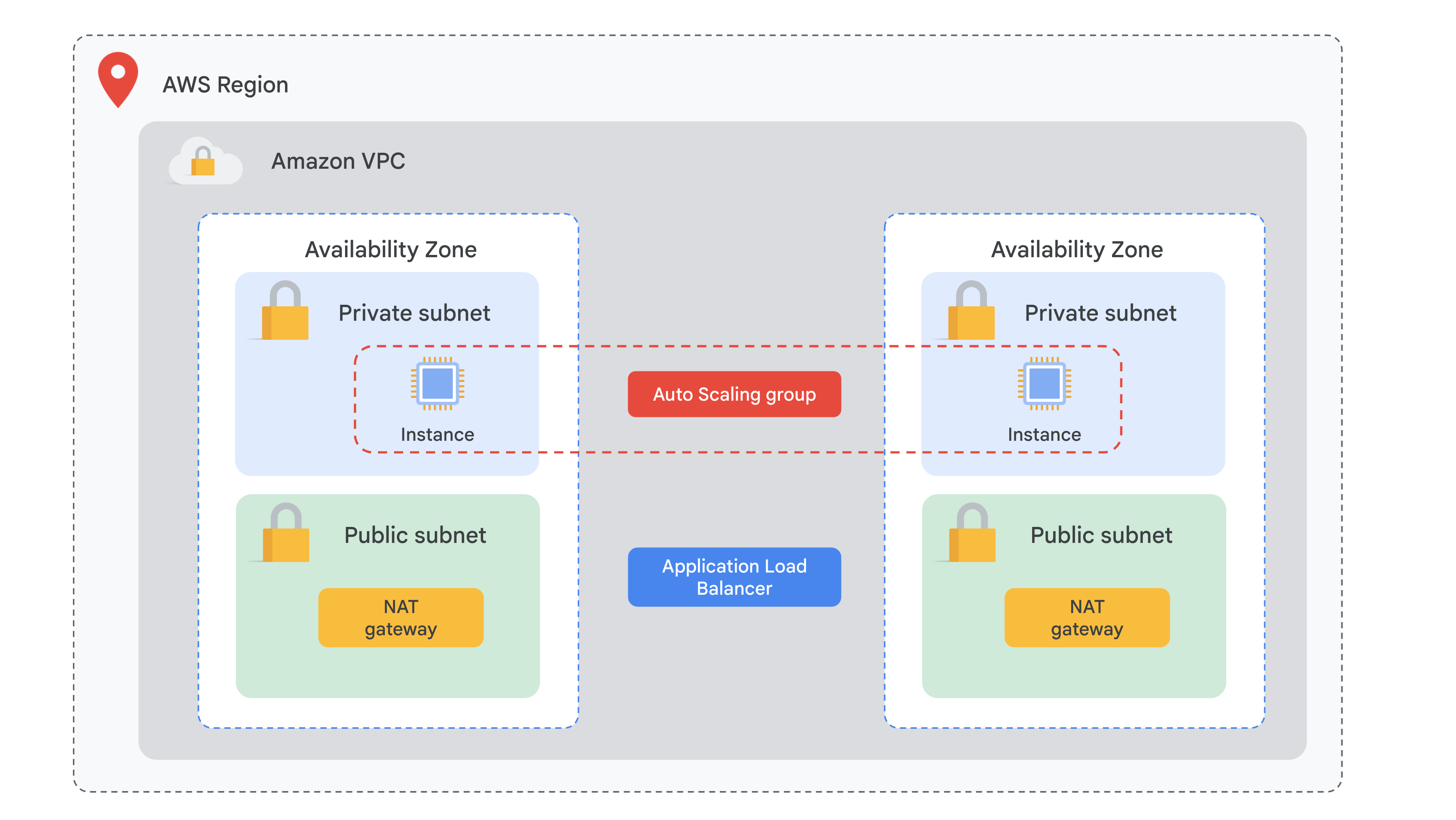
As a cloud engineer, your main objective is to build fault-tolerant, reliable, highly available, and cost-effective systems in the cloud. You want to design auto-scalable solutions that can respond to spikes in demand. You ensure that your architecture design is not over-provisioned and helps your organization optimize costs. In general, you take the following into consideration as you complete your designs:
In AWS, you have built scaling plans that automate how groups of different Elastic Compute Cloud (EC2) resources respond to changes in demand. To accomplish this you have used the following:
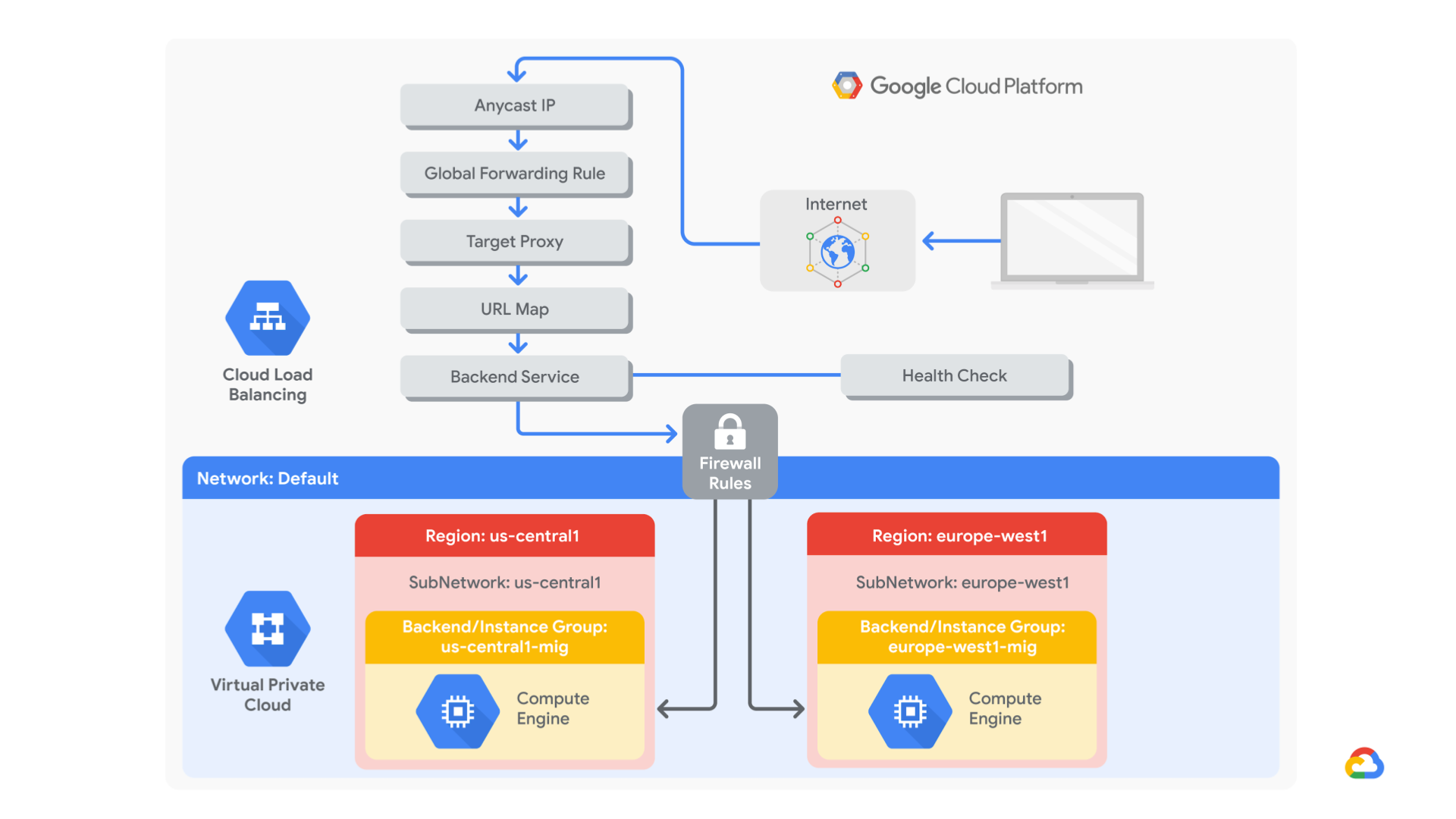
Now you will explore different services within Google Cloud that will help you build a highly available and scalable solution.
Application Load Balancing (HTTP/HTTPS) is implemented at the edge of Google's network in Google's points of presence (POP) around the world. User traffic directed to an Application Load Balancer (HTTP/HTTPS) enters the POP closest to the user and is then load-balanced over Google's global network to the closest backend that has sufficient available capacity.
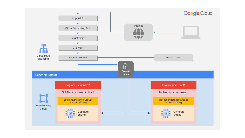
In this lab, you configure an Application Load Balancer (HTTP) as shown in the diagram below. Then, you stress test the load balancer to demonstrate global load balancing and autoscaling.
In this lab, you learn how to perform the following tasks:
For each lab, you get a new Google Cloud project and set of resources for a fixed time at no cost.
Click the Start Lab button. If you need to pay for the lab, a pop-up opens for you to select your payment method. On the left is the Lab Details panel with the following:
Click Open Google Cloud console (or right-click and select Open Link in Incognito Window if you are running the Chrome browser).
The lab spins up resources, and then opens another tab that shows the Sign in page.
Tip: Arrange the tabs in separate windows, side-by-side.
If necessary, copy the Username below and paste it into the Sign in dialog.
You can also find the Username in the Lab Details panel.
Click Next.
Copy the Password below and paste it into the Welcome dialog.
You can also find the Password in the Lab Details panel.
Click Next.
Click through the subsequent pages:
After a few moments, the Google Cloud console opens in this tab.
In this task, you configure a firewall rule to allow health check traffic to your instances.
Health checks determine which instances of a Application Load Balancer (HTTP) can receive new connections. The health check probes to your load-balanced instances come from addresses in the ranges 130.211.0.0/22 and 35.191.0.0/16. Your firewall rules must allow these connections.
Create a firewall rule to allow health checks.
In the Cloud console, in the Navigation menu (
Notice the existing ICMP, internal, RDP, and SSH firewall rules.
Each Google Cloud project starts with the default network and these firewall rules.
Click Create Firewall Rule.
Specify the following, and leave the remaining settings as their defaults:
| Property | Value (type value or select option as specified) |
|---|---|
| Name | fw-allow-health-checks |
| Network | default |
| Targets | Specified target tags |
| Target tags | allow-health-checks |
| Source filter | IPv4 ranges |
| Source IPv4 ranges | 130.211.0.0/22 and 35.191.0.0/16 |
| Protocols and ports | Specified protocols and ports |
Click Check my progress to verify the objective.
In this task, you create a Cloud Router instance and configure a Cloud NAT gateway to enable outbound internet connectivity for your VM instances.
The Google Cloud VM backend instances that you set up in Task 3 will not be configured with external IP addresses.
Instead, you will set up the Cloud NAT service to allow these VM instances to send outbound traffic only through the Cloud NAT, and receive inbound traffic through the load balancer.
On the Google Cloud console title bar, type Network services in the Search field, then click Network services in the Network management tools section.
On the Network service page, click Pin next to Network services.
Click Cloud NAT.
Click Get started to configure a NAT gateway.
Specify the following, and leave the remaining settings as their defaults:
| Property | Value (type value or select option as specified) |
|---|---|
| Gateway name | nat-config |
| Network | default |
| Region |
Click Cloud Router, and select Create new router.
For Name, type nat-router-us1.
Click Create.
In Create a NAT gateway, click Create.
Click Check my progress to verify the objective.
In this task, you create a custom web server image for the backend of the load balancer.
In the Cloud Console, in the Navigation menu (
Click Create Instance.
Specify the following, and leave the remaining settings as their defaults:
| Property | Value (type value or select option as specified) |
|---|---|
| Name | webserver |
| Region | |
| Zone |
Click OS and storage, and then click Change.
Click Show Advanced Configuration.
For Deletion rule, select Keep boot disk.
Click Select.
Click Networking.
Click Done.
Click Create.
The default page for the Apache2 server should be displayed.
The software installation was successful. However, when a new VM is created using this image, the freshly booted VM does not have the Apache web server running. Use the following command to set the Apache service to automatically start on boot. Then test it to make sure it works.
In the Cloud console, select webserver, and then click More actions 
Click Reset.
In the confirmation dialog, click Reset.
Verify that the boot disk will not be deleted when the instance is deleted.
) .In the left pane, click Images.
Click Create image.
Specify the following, and leave the remaining settings as their defaults:
| Property | Value (type value or select option as specified) |
|---|---|
| Name | mywebserver |
| Source | Disk |
| Source disk | webserver |
Click Create.
The next step is to use that image to define an instance template that can be used in the managed instance groups.
Click Check my progress to verify the objective.
In this task, you configure instance templates and create managed instance groups for your load-balanced web server.
A managed instance group uses an instance template to create a group of identical instances. Use these to create the backends of the Application Load Balancer (HTTP).
An instance template is an API resource that you can use to create VM instances and managed instance groups. Instance templates define the machine type, boot disk image, subnet, labels, and other instance properties.
), click Compute Engine > Instance templates.On the Navigation menu, click Compute Engine > Health checks.
Click Create health check.
Specify the following, and leave the remaining settings as their defaults:
| Property | Value (select option as specified) |
|---|---|
| Name | http-health-check |
| Protocol | TCP |
| Port | 80 |
Click Create.
Create a managed instance group in
On the Navigation menu, click Compute Engine > Instance groups.
Click Create Instance Group.
Specify the following, and leave the remaining settings as their defaults:
| Property | Value (type value or select option as specified) |
|---|---|
| Name | us-1-mig |
| Instance template | mywebserver-template |
| Location | Multiple zones |
| Region |
For Autoscaling, enter Minimum number of instances 1 and Maximum number of instances 2.
For Autoscaling signals, click on the CPU utilization.
For Signal type, select HTTP load balancing utilization.
Enter Target HTTP load balancing utilization to 80.
Click Done.
Click Initialization period and set to 60 seconds.
In Autohealing, for health check type http-health-check
Select http-health-check (TCP)
For Initial delay, type 60.
This is how long the Instance Group waits after initializing the boot-up of a VM before it tries a health check. You don't want to wait 5 minutes for this during the lab, so you set it to 1 minute.
Click Create.
Click Confirm in the dialog window.
Click Create Instance Group.
Specify the following, and leave the remaining settings as their defaults:
| Property | Value (type value or select option as specified) |
|---|---|
| Name | notus-1-mig |
| Instance template | mywebserver-template |
| Location | Multiple zones |
| Region | |
| Autoscaling > Minimum number of instances | 1 |
| Autoscaling > Maximum number of instances | 2 |
| Autoscaling signals > Signal Type | HTTP load balancing utilization |
| Target HTTP load balancing utilization | 80 |
| Initialization period | 60 |
For Health check, select http-health-check (TCP).
For Initial delay, type 60.
Click Create.
Click Confirm in the dialog window.
Click Check my progress to verify the objective.
Verify that VM instances are being created in both regions.
In this task, you configure the Application Load Balancer (HTTP) to balance traffic between the two backends (us-1-mig in
The host and path rules determine how your traffic will be directed. For example, you could direct video traffic to one backend and direct static traffic to another backend. However, you are not configuring the host and path rules in this lab.
Click Frontend configuration.
Specify the following, and leave the remaining settings as their defaults:
| Property | Value (type value or select option as specified) |
|---|---|
| Protocol | HTTP |
| IP version | IPv4 |
| IP address | Ephemeral |
| Port | 80 |
Click Done.
Click Add Frontend IP and Port.
Specify the following, and leave the remaining settings as their defaults:
| Property | Value (type value or select option as specified) |
|---|---|
| Protocol | HTTP |
| IP version | IPv6 |
| IP address | Auto-Allocate |
| Port | 80 |
Click Done.
Backend services direct incoming traffic to one or more attached backends. Each backend is composed of an instance group and additional serving capacity metadata.
Click Backend Configuration.
Click Backend services & backend buckets > Create a Backend Service.
Specify the following, and leave the remaining settings as their defaults:
| Property | Value (select option as specified) |
|---|---|
| Name | http-backend |
| Backend type | Instance group |
| Instance group | us-1-mig |
| Port numbers | 80 |
| Balancing mode | Rate |
| Maximum RPS | 50 |
| Capacity | 100 |
Click Done.
Click Add Backend.
Specify the following, and leave the remaining settings as their defaults:
| Property | Value (select option as specified) |
|---|---|
| Instance group | notus-1-mig |
| Port numbers | 80 |
| Balancing mode | Utilization |
| Maximum backend utilization | 80 |
| Capacity | 100 |
1.[LB_IP_v4] and [LB_IP_v6], respectively.Click Check my progress to verify the objective.
In this task, you stress test your Application Load Balancer (HTTP) to verify that traffic is forwarded to the backend service.
 ).
).http://[LB_IP_v4]. Make sure to replace [LB_IP_v4] with the IPv4 address of the load balancer.Create a new VM to simulate a load on the Application Load Balancer (HTTP). Then determine whether traffic is balanced across both backends when the load is high.
In the Cloud console, on the Navigation menu (
Click Create instance.
Specify the following, and leave the remaining settings as their defaults:
| Property | Value (type value or select option as specified) |
|---|---|
| Name | stress-test |
| Region | A region different but closer to |
| Zone | A zone from the region |
For Series, select E2.
For Machine type, select e2-micro (2 vCPU, 1 core, 1 GB memory).
Click Check my progress to verify the objective.
), click Network Services > Load balancing.), click Compute Engine > Instance groups.In this lab, you configured an Application Load Balancer (HTTP) with backends in
In AWS, a common pattern for a highly available architecture includes the following:
In Google Cloud, you can use the following services to achieve high availability (HA) in your workloads:
Also, you can choose from regional or, in the case of an external load balancer, global load balancing. An additional aspect to consider when selecting an appropriate load balancer is the type of traffic, for example TCP/UDP, HTTP and HTTPS, or SSL.
When you have completed your lab, click End Lab. Qwiklabs removes the resources you’ve used and cleans the account for you.
You will be given an opportunity to rate the lab experience. Select the applicable number of stars, type a comment, and then click Submit.
The number of stars indicates the following:
You can close the dialog box if you don't want to provide feedback.
For feedback, suggestions, or corrections, please use the Support tab.
Copyright 2022 Google LLC All rights reserved. Google and the Google logo are trademarks of Google LLC. All other company and product names may be trademarks of the respective companies with which they are associated.


This content is not currently available
We will notify you via email when it becomes available
Great!
We will contact you via email if it becomes available

One lab at a time
Confirm to end all existing labs and start this one