Before you begin
- Labs create a Google Cloud project and resources for a fixed time
- Labs have a time limit and no pause feature. If you end the lab, you'll have to restart from the beginning.
- On the top left of your screen, click Start lab to begin
Configure a health check firewall rule
/ 10
Create two NAT configurations using Cloud Router
/ 10
Configure an instance template and create instance groups
/ 10
Configure the HTTP Load Balancer
/ 10
Deny the siege-vm
/ 10
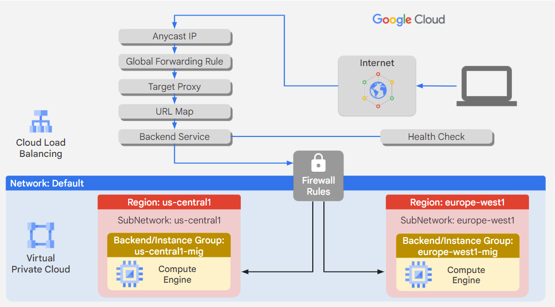
Google Cloud HTTP(S) load balancing is implemented at the edge of Google's network in Google's points of presence (POP) around the world. User traffic directed to an HTTP(S) load balancer enters the POP closest to the user and is then load-balanced over Google's global network to the closest backend that has sufficient capacity available.
Google Cloud Armor IP deny/allow rules enable you to restrict or allow access to your HTTP(S) load balancer at the edge of the Google Cloud, as close as possible to the user and to malicious traffic. This prevents malicious users or traffic from consuming resources or entering your virtual private cloud (VPC) networks.
In this lab, you will configure an HTTP load balancer with global backends, as shown in the diagram below. Then you stress test the load balancer and deny the stress test IP with Google Cloud Armor.
In this lab, you will learn how to perform the following tasks:
For each lab, you get a new Google Cloud project and set of resources for a fixed time at no cost.
Sign in to Qwiklabs using an incognito window.
Note the lab's access time (for example, 1:15:00), and make sure you can finish within that time.
There is no pause feature. You can restart if needed, but you have to start at the beginning.
When ready, click Start lab.
Note your lab credentials (Username and Password). You will use them to sign in to the Google Cloud Console.
Click Open Google Console.
Click Use another account and copy/paste credentials for this lab into the prompts.
If you use other credentials, you'll receive errors or incur charges.
Accept the terms and skip the recovery resource page.
Google Cloud Shell is a virtual machine that is loaded with development tools. It offers a persistent 5GB home directory and runs on the Google Cloud.
Google Cloud Shell provides command-line access to your Google Cloud resources.
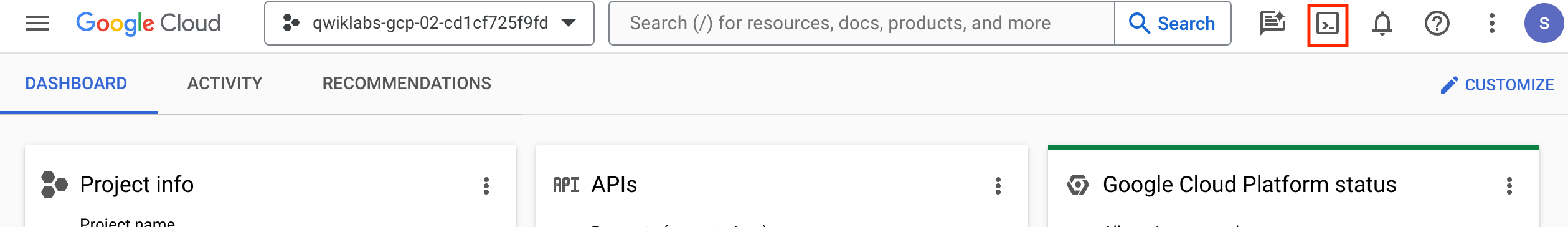
In Cloud console, on the top right toolbar, click the Open Cloud Shell button.
Click Continue.
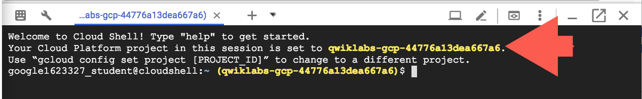
It takes a few moments to provision and connect to the environment. When you are connected, you are already authenticated, and the project is set to your PROJECT_ID. For example:
gcloud is the command-line tool for Google Cloud. It comes pre-installed on Cloud Shell and supports tab-completion.
Output:
Example output:
Output:
Example output:
Health checks determine which instances of a load balancer can receive new connections. For HTTP load balancing, the health check probes to your load-balanced instances come from addresses in the ranges 130.211.0.0/22 and 35.191.0.0/16. Your firewall rules must allow these connections.
Create a firewall rule to allow HTTP traffic to the backends.
In the Cloud console, navigate to Navigation menu (
Notice the existing ICMP, internal, RDP, and SSH firewall rules.
Each Google Cloud project starts with the default network and these firewall rules.
Click Create Firewall Rule.
Set the following values, leave all other values at their defaults:
| Property | Value (type value or select option as specified) |
|---|---|
| Name | default-allow-http |
| Network | default |
| Targets | Specified target tags |
| Target tags | http-server |
| Source filter | IPv4 Ranges |
| Source IPv4 ranges | 0.0.0.0/0 |
| Protocols and ports | Specified protocols and ports, and then check TCP, type: 80 |
Make sure to include the /0 in the Source IPv4 ranges to specify all networks.
Health checks determine which instances of a load balancer can receive new connections. For Application Load Balancing, the health check probes to your load balanced instances come from addresses in the ranges 130.211.0.0/22 and 35.191.0.0/16. Your firewall rules must allow these connections.
Still in the Firewall policies page, click Create Firewall Rule.
Set the following values, leave all other values at their defaults:
| Property | Value (type value or select option as specified) |
|---|---|
| Name | default-allow-health-check |
| Network | default |
| Targets | Specified target tags |
| Target tags | http-server |
| Source filter | IPv4 Ranges |
| Source IPv4 ranges |
130.211.0.0/22, 35.191.0.0/16
|
| Protocols and ports | Specified protocols and ports, and then check TCP |
Click Create.
Click Check my progress to verify the objective.
The Google Cloud VM backend instances that you set up in task 3 will not be configured with external IP addresses.
Instead, you will set up the Cloud NAT service to allow these VM instances to make outbound requests in order to install Apache Web server and PHP when they are launched. You create a Cloud Router for each managed instance group, one in
In the Cloud Console, in the Navigation menu (
Click Get started.
Specify the following, and leave the remaining settings as their defaults:
| Property | Value (type value or select option as specified) |
|---|---|
| Gateway name | nat-1 |
| Network | default |
| Region |
Click Cloud Router and select Create new router.
For Name, type nat-router-1.
Click Create.
In Create a cloud NAT gateway, click Create.
Repeat the same procedure for nat-2.
Click Create Cloud NAT Gateway.
Specify the following, and leave the remaining settings as their defaults:
| Property | Value (type value or select option as specified) |
|---|---|
| Gateway name | nat-2 |
| Network | default |
| Region | |
| Cloud Router > Create new router | Specify the name nat-router-2
|
Click Create.
In Create a NAT gateway, click Create.
Click Check my progress to verify the objective.
A managed instance group uses an instance template to create a group of identical instances. You will use these to create the backends of the HTTP load balancer.
An instance template is an API resource that you can use to create VM instances and managed instance groups. Instance templates define the machine type, boot disk image, subnet, labels, and other instance properties.
In the Cloud Console, in the Navigation menu (
Click Create instance template.
For Name, type template-1.
Choose Region :
Click Advanced Options.
Click Management.
Under Metadata, click + ADD ITEM and specify the following:
| Key | Value |
|---|---|
| startup-script-url | gs://cloud-training/gcpnet/httplb/startup.sh |
Click Networking.
Specify the following, and leave the remaining settings as their defaults:
| Property | Value (type value or select option as specified) |
|---|---|
| Network tags | allow-health-checks |
| Network interface > Network | default |
| Subnetwork | default ( |
| External IPv4 address | None |
Click DONE.
Click Create. Wait for the instance template to be created.
Now, prepare to create another instance template by copying template-1. Click the template-1. Information about the template-1 appears.
Near the top of the page, click CREATE SIMILAR.
For Name, type template-2.
Choose Region :
Click Advanced Options.
Click Networking > Network interface.
Select default
Click Create.
Create a managed instance group in
In the Navigation menu, select Compute Engine > Instance groups.
Click Create Instance group.
Specify the following, and leave the remaining settings as their defaults:
| Property | Value (type value or select option as specified) |
|---|---|
| Name | mig-1 |
| Instance template | template-1 |
| Location | Multiple zones |
| Region | |
| Autoscaling > Minimum number of instances | 1 |
| Autoscaling > Maximum number of instances | 5 |
| Autoscaling > Autoscaling signals | Click CPU utilization, set Target CPU utilization 80 |
| Initialization period | 45 |
Click Create.
Repeat the same procedure for mig-2 in
Click Create Instance group.
Specify the following, and leave the remaining settings as their defaults:
| Property | Value (type value or select option as specified) |
|---|---|
| Name | mig-2 |
| Location | Multiple zones |
| Region | |
| Instance template | template-2 |
| Autoscaling > Minimum number of instances | 1 |
| Autoscaling > Maximum number of instances | 5 |
| Autoscaling > Autoscaling signals | Click CPU utilization, set Target CPU utilization 80 |
| Initialization period | 45 |
Click Create.
Click Check my progress to verify the objective.
Verify that VM instances are being created in both regions and access their HTTP sites.
In the Navigation menu, click Compute Engine > VM instances.
Notice the instances that start with mig-1 and mig-2.
These instances are part of the managed instance groups.
In Cloud Console, note the name and the zone of the VM instance located in
On the Google Cloud Platform menu, click Activate Cloud Shell (
In Cloud Shell, execute this command to execute SSH commands in the VM instance located in
Y.You should see the Apache welcome page, which was installed as part of the startup-script-url script that changes the welcome page to include the client IP and the name, region, and zone of the VM instance.
exit to close the SSH session.Next, you will configure the HTTP load balancer to balance traffic between the two backends (mig-1 in
) click View All Products and navigate to Network services > Load balancing.Backend services direct incoming traffic to one or more attached backends. Each backend is composed of an instance group and additional serving capacity metadata.
Click Backend configuration.
For Backend services & backend buckets, click Create a backend service.
Specify the following, and leave the remaining settings as their defaults:
| Property | Value (select option as specified) |
|---|---|
| Name | http-backend |
| Backend type | Instance group |
| Backends > Instance group | mig-1 |
| Port numbers | 80 |
| Balancing mode | Rate |
| Maximum RPS | 50 |
| Capacity | 100 |
Click Done.
Click Add backend.
Specify the following, and leave the remaining settings as their defaults:
| Property | Value (select option as specified) |
|---|---|
| Instance group | mig-2 |
| Port numbers | 80 |
| Balancing mode | Utilization |
| Maximum backend utilization | 80 |
| Capacity | 100 |
Click Done.
For Health Check, select Create a health check.
Specify the following, and leave the remaining settings as their defaults:
| Property | Value (select option as specified) |
|---|---|
| Name | http-health-check |
| Protocol | TCP |
| Port | 80 |
1.The host and path rules determine how your traffic will be directed. For example, you could direct video traffic to one backend and direct static traffic to another backend. However, you are not configuring the host and path rules in this lab.
Click Frontend configuration.
Specify the following, and leave the remaining settings as their defaults:
| Property | Value (type value or select option as specified) |
|---|---|
| Protocol | HTTP |
| IP version | IPv4 |
| IP address | Ephemeral |
| Port | 80 |
Click Done.
Click Add Frontend IP and port.
Specify the following, and leave the remaining settings as their defaults:
| Property | Value (type value or select option as specified) |
|---|---|
| Protocol | HTTP |
| IP version | IPv6 |
| IP address | Auto-allocate |
| Port | 80 |
Click Done.
[LB_IP_v4] and [LB_IP_v6], respectively.Click Check my progress to verify the objective.
Now that you have created the HTTP load balancer for your backends, it is time to verify that traffic is forwarded to the backend service.
http://[LB_IP_v4]. Make sure to replace [LB_IP_v4] with the IPv4 address of the load balancer.http://[LB_IP_v6]. Make sure to replace [LB_IP_v6] with the IPv6 address of the load balancer.Next, you will create a new VM to simulate a load on the HTTP load balancer. Then you will determine whether traffic is balanced across both backends when the load is high.
In the Cloud Console, in the Navigation menu (
Click Create instance.
Specify the following, and leave the remaining settings as their defaults:
| Property | Value (type value or select option as specified) |
|---|---|
| Name | siege-vm |
| Region | |
| Zone |
Click Create. Wait for the siege-vm instance to be created.
At the Cloud Shell prompt, enter the following command to create an SSH connection to the siege-vm:
Run the following command to install siege:
[LB_IP_v4] with the IPv4 address:) click View All Products and navigate to Network services > Load balancing.The output should look like this.
Output:
You will now use Google Cloud Armor to deny the siege-vm from accessing the HTTP load balancer.
Create a Google Cloud Armor security policy with a deny rule for the siege-vm.
[SIEGE_IP].In the Navigation menu (
Click Create policy.
Specify the following, and leave the remaining settings as their defaults:
| Property | Value (type value or select option as specified) |
|---|---|
| Name | deny-siege |
| Default rule action | Allow |
Click Next step.
Click Add rule.
Specify the following, and leave the remaining settings as their defaults:
| Property | Value (type value or select option as specified) |
|---|---|
| Condition > Match | Enter the SIEGE_IP |
| Action | Deny |
| Deny status | 403 (Forbidden) |
| Priority | 1000 |
Click Save change to rule.
Click Next step.
Click Add Target.
For Type, select Backend service (external application load balancer).
For Target, select http-backend and if prompted confirm Replace.
Click Create policy.
Wait for the policy to be created before moving to the next step.
Click Check my progress to verify the objective.
Next, you will verify that the siege-vm cannot access the HTTP load balancer.
The output should look like this.
Output:
http://[LB_IP_v4]. Make sure to replace [LB_IP_v4] with the IPv4 address of the load balancer.The command will not generate any output.
Explore the security policy logs to determine whether this traffic is also blocked.
) click View All Products and navigate to Network Security > Cloud Armor > Cloud Armor policies.The request should be from the siege-vm IP address. If not, expand another log entry.
DENY with the name deny-siege.In this lab, you have configured an HTTP load balancer with backends in
When you have completed your lab, click End Lab. Google Cloud Skills Boost removes the resources you’ve used and cleans the account for you.
You will be given an opportunity to rate the lab experience. Select the applicable number of stars, type a comment, and then click Submit.
The number of stars indicates the following:
You can close the dialog box if you don't want to provide feedback.
For feedback, suggestions, or corrections, please use the Support tab.
Copyright 2024 Google LLC All rights reserved. Google and the Google logo are trademarks of Google LLC. All other company and product names may be trademarks of the respective companies with which they are associated.


This content is not currently available
We will notify you via email when it becomes available
Great!
We will contact you via email if it becomes available
One lab at a time
Confirm to end all existing labs and start this one